

Metal-seated ball valve · Chinese standard · Made in Wenzhou
GB/T 12237 Metal-Seated Ball Valve — Lever Operated
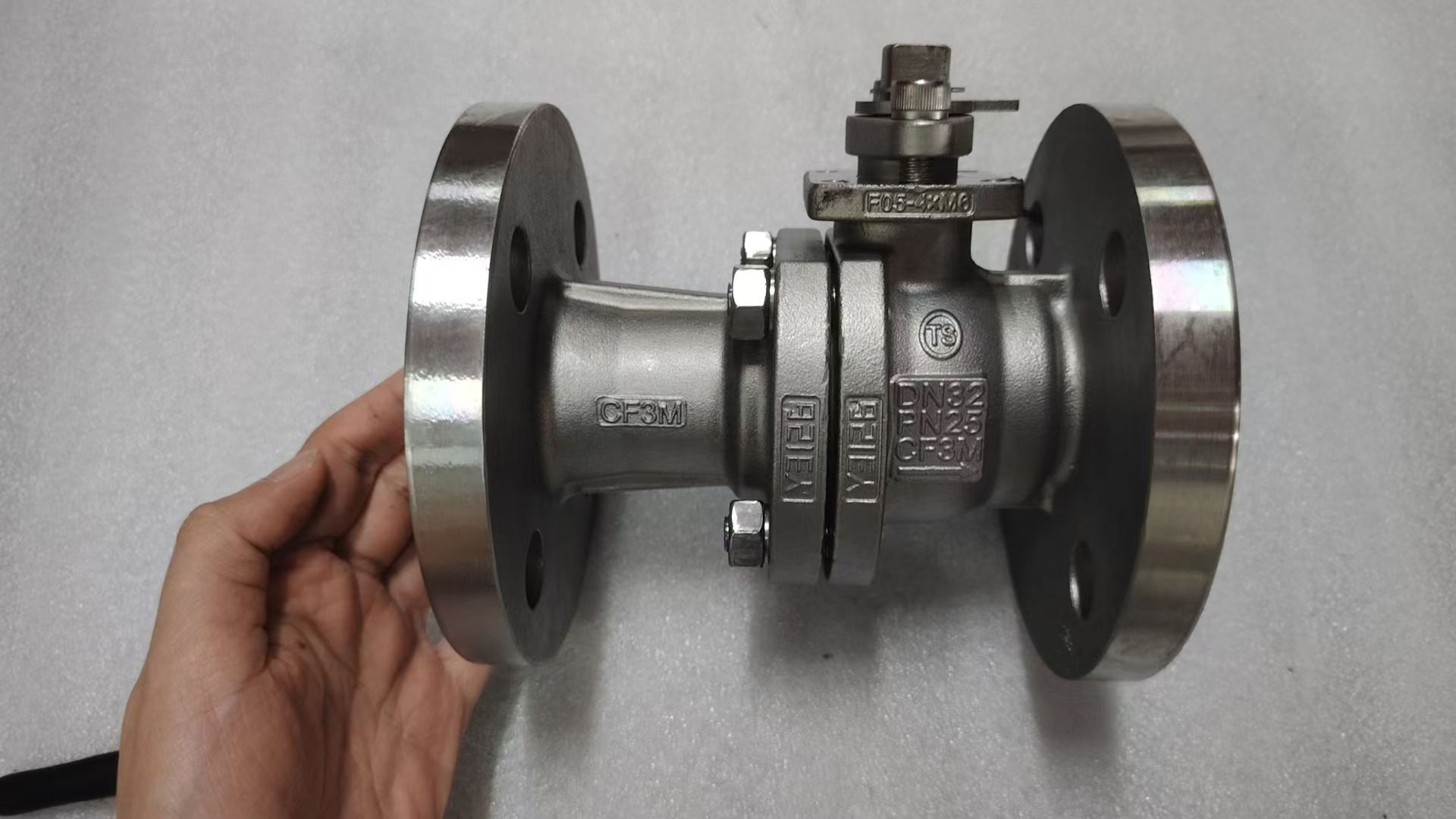
Flanged floating ball valve to the Chinese national standard GB/T 12237, with a hardfaced ball and metal seats instead of PTFE, for lines up to +420 °C or media with particles that would wear out a soft seat. PN16 to PN40, DN15 to DN200, opened and closed by a quarter-turn hand lever.
- Hardfaced ball and seats for hot media and media with solid particles
- Every valve shell and seat tested per JB/T 9092, test report in every shipment
- Standard sizes ship in 15–20 days
An engineer replies within 24 hours. Send size, PN, material and quantity. Download GA drawing (PDF) →
Specifications
Technical Data
| Design standard | GB/T 12237 |
| Face-to-face | GB/T 12221 |
| Flanges | HG/T 20592, raised face |
| Size range | DN15–DN200 |
| Pressure rating | PN16 / PN25 / PN40 |
| Body material | WCB (A216) · CF8 (A351) · CF3M (A351) |
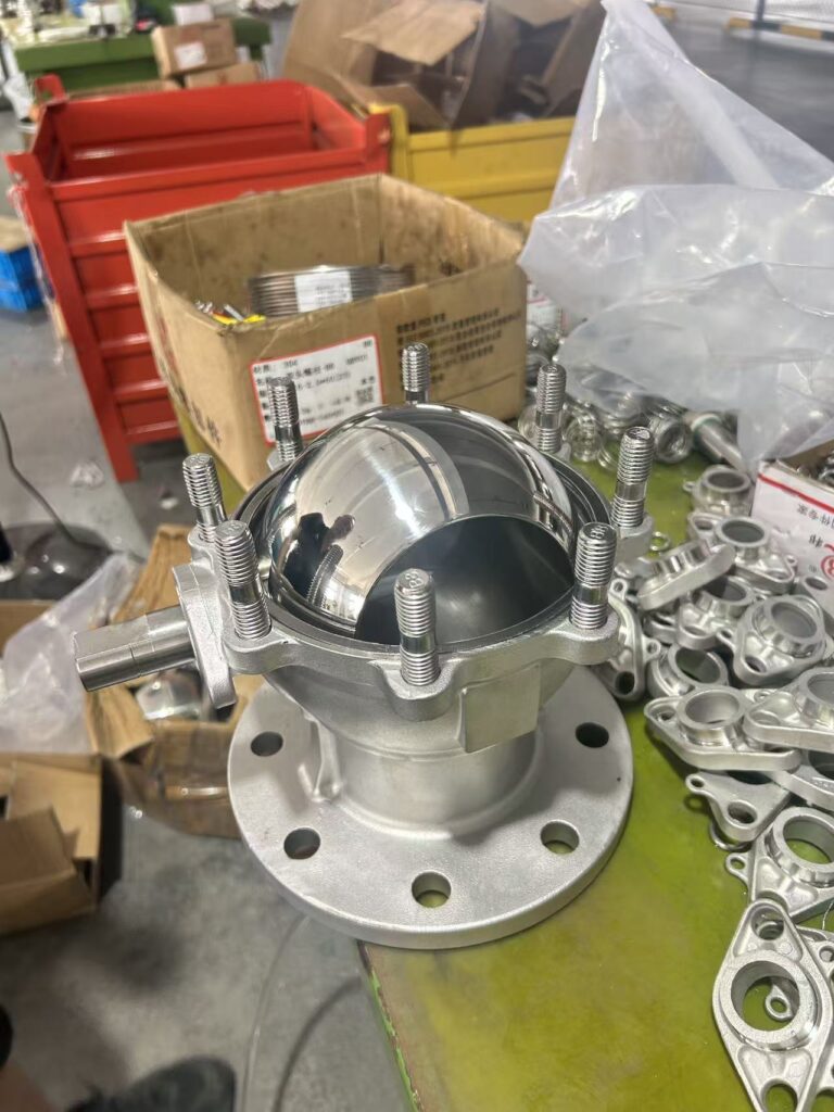
| Ball and seats | Stainless steel (F304 / F316L), hardfaced to suit the service: hard chrome plating (HCr), nickel alloy (Ni55 / Ni60), tungsten carbide (WC) or Stellite (STL) |
| Temperature | −29 °C to +420 °C (limited by body material and pressure) |
| Gasket and packing | Spiral-wound gasket, flexible graphite packing |
| Construction | Two-piece body, floating ball |
| Top flange | Drilled to ISO 5211 (F05–F14), see dimension table |
| Operation | Quarter-turn hand lever; actuator with bracket and coupling |
| Media | Water, oil and gas |
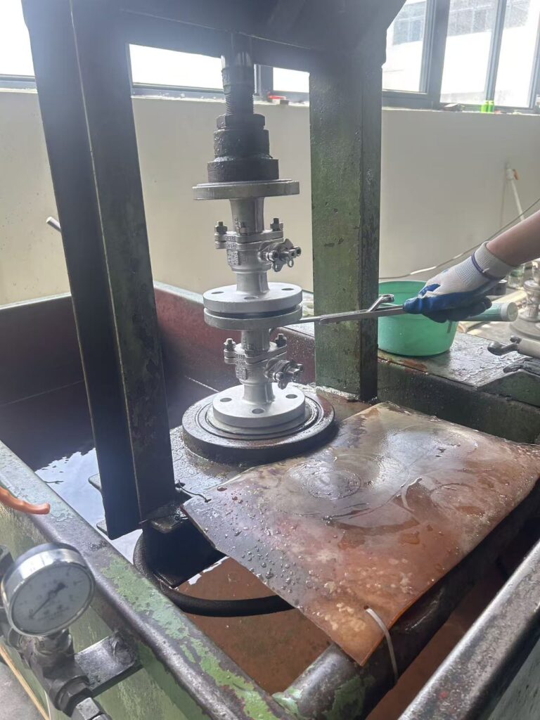
| Testing | JB/T 9092 — every valve |
Application
Where It Is Used
For lines built to Chinese standards where the temperature or the media would damage a PTFE seat. Below +150 °C with clean media, a soft-seated valve seals tighter and costs less.
- Hot oil and thermal oil lines
- High-temperature water and gas lines
- Media carrying particles or scale that would cut a PTFE seat
- Projects and plants designed to GB standards
- Chemical lines (CF3M body)
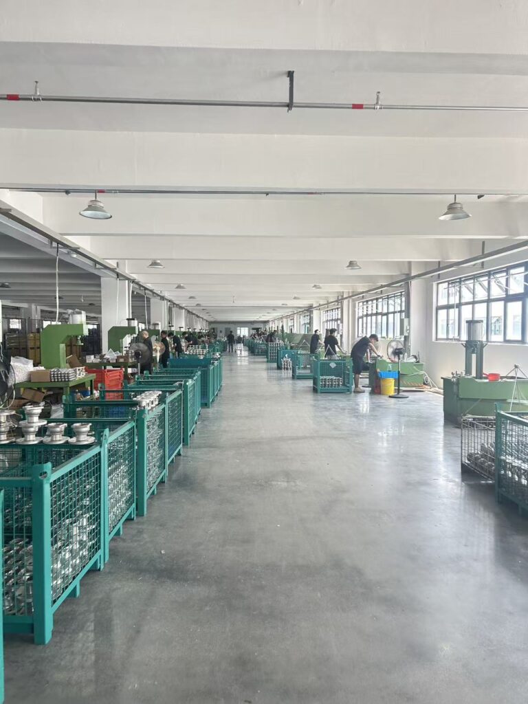 ASSEMBLY HALL · WENZHOU
Dimensions
Dimensions (mm)
PN16 — flange and length
| DN | NPS | L | D | D1 | D2 | T | f | n-Ød |
|---|---|---|---|---|---|---|---|---|
| 15 | ½″ | 130 | 95 | 65 | 45 | 16 | 2 | 4-Ø14 |
| 20 | ¾″ | 130 | 105 | 75 | 58 | 18 | 2 | 4-Ø14 |
| 25 | 1″ | 140 | 115 | 85 | 68 | 18 | 2 | 4-Ø14 |
| 32 | 1¼″ | 165 | 140 | 100 | 78 | 18 | 2 | 4-Ø18 |
| 40 | 1½″ | 165 | 150 | 110 | 88 | 18 | 2 | 4-Ø18 |
| 50 | 2″ | 203 | 165 | 125 | 102 | 18 | 2 | 4-Ø18 |
| 65 | 2½″ | 222 | 185 | 145 | 122 | 18 | 2 | 8-Ø18 |
| 80 | 3″ | 241 | 200 | 160 | 138 | 20 | 2 | 8-Ø18 |
| 100 | 4″ | 305 | 220 | 180 | 158 | 20 | 2 | 8-Ø18 |
| 125 | 5″ | 356 | 250 | 210 | 188 | 22 | 2 | 8-Ø18 |
| 150 | 6″ | 394 | 285 | 240 | 212 | 22 | 2 | 8-Ø22 |
| 200 | 8″ | 457 | 340 | 295 | 268 | 24 | 2 | 12-Ø22 |
PN25 — flange and length
| DN | NPS | L | D | D1 | D2 | T | f | n-Ød |
|---|---|---|---|---|---|---|---|---|
| 15 | ½″ | 130 | 95 | 65 | 45 | 16 | 2 | 4-Ø14 |
| 20 | ¾″ | 130 | 105 | 75 | 58 | 18 | 2 | 4-Ø14 |
| 25 | 1″ | 140 | 115 | 85 | 68 | 18 | 2 | 4-Ø14 |
| 32 | 1¼″ | 165 | 140 | 100 | 78 | 18 | 2 | 4-Ø18 |
| 40 | 1½″ | 165 | 150 | 110 | 88 | 18 | 2 | 4-Ø18 |
| 50 | 2″ | 203 | 165 | 125 | 102 | 20 | 2 | 4-Ø18 |
| 65 | 2½″ | 241 | 185 | 145 | 122 | 22 | 2 | 8-Ø18 |
| 80 | 3″ | 283 | 200 | 160 | 138 | 24 | 2 | 8-Ø18 |
| 100 | 4″ | 305 | 235 | 190 | 162 | 24 | 2 | 8-Ø22 |
| 125 | 5″ | 381 | 270 | 220 | 188 | 26 | 2 | 8-Ø26 |
| 150 | 6″ | 403 | 300 | 250 | 218 | 28 | 2 | 8-Ø26 |
| 200 | 8″ | 502 | 360 | 310 | 278 | 30 | 2 | 12-Ø26 |
PN40 — flange and length
| DN | NPS | L | D | D1 | D2 | T | f | n-Ød |
|---|---|---|---|---|---|---|---|---|
| 15 | ½″ | 140 | 95 | 65 | 45 | 16 | 2 | 4-Ø14 |
| 20 | ¾″ | 152 | 105 | 75 | 58 | 18 | 2 | 4-Ø14 |
| 25 | 1″ | 165 | 115 | 85 | 68 | 18 | 2 | 4-Ø14 |
| 32 | 1¼″ | 178 | 140 | 100 | 78 | 18 | 2 | 4-Ø18 |
| 40 | 1½″ | 190 | 150 | 110 | 88 | 18 | 2 | 4-Ø18 |
| 50 | 2″ | 216 | 165 | 125 | 102 | 20 | 2 | 4-Ø18 |
| 65 | 2½″ | 241 | 185 | 145 | 122 | 22 | 2 | 8-Ø18 |
| 80 | 3″ | 283 | 200 | 160 | 138 | 24 | 2 | 8-Ø18 |
| 100 | 4″ | 305 | 235 | 190 | 162 | 24 | 2 | 8-Ø22 |
| 125 | 5″ | 381 | 270 | 220 | 188 | 26 | 2 | 8-Ø26 |
| 150 | 6″ | 403 | 300 | 250 | 218 | 28 | 2 | 8-Ø26 |
| 200 | 8″ | 502 | 375 | 320 | 285 | 34 | 2 | 12-Ø30 |
Top works — PN16, PN25 and PN40
| DN | NPS | Stem F × ØY | Top flange ØE / ISO 5211 | Top flange bolts | Lever M |
|---|---|---|---|---|---|
| 15 | ½″ | 9×Ø14 | 50 / F05 | 4-M6 | 160 |
| 20 | ¾″ | 9×Ø14 | 50 / F05 | 4-M6 | 160 |
| 25 | 1″ | 10×Ø16 | 50 / F05 | 4-M6 | 180 |
| 32 | 1¼″ | 10×Ø16 | 50 / F05 | 4-M6 | 180 |
| 40 | 1½″ | 14×Ø20 | 70 / F07 | 4-M8 | 230 |
| 50 | 2″ | 14×Ø20 | 70 / F07 | 4-M8 | 230 |
| 65 | 2½″ | 16×Ø24 | 90 / F09 | 4-M10 | 270 |
| 80 | 3″ | 17×Ø26 | 90 / F09 | 4-M10 | 310 |
| 100 | 4″ | 17×Ø26 | 90 / F09 | 4-M10 | 310 |
| 125 | 5″ | 21×Ø32 | 102 / F10 | 4-M10 | 600 |
| 150 | 6″ | 24×Ø36 | 125 / F12 | 4-M12 | 700 |
| 200 | 8″ | 27×Ø40 | 140 / F14 | 4-M16 | 800 |
From our Q41Y PN16, PN25 and PN40 general assembly drawings. L = face-to-face (GB/T 12221) · D = flange O.D. · D1 = bolt circle · D2 = raised face O.D. · T = flange thickness · f = raised face height · n-Ød = bolt holes · Stem F × ØY = stem flats × stem diameter · ØE = top flange bolt circle · M = lever length. Flanges to HG/T 20592.
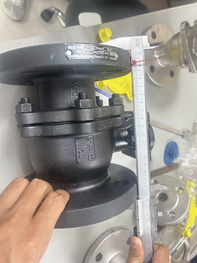 FACE-TO-FACE CHECK
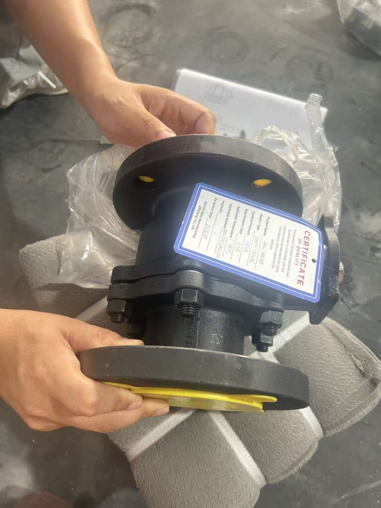 QC TAG ON EVERY VALVE
Checked before packing
Face-to-face and flange dimensions are checked with calipers against GB/T 12221 and HG/T 20592 before packing. Each valve gets a QC tag with model, size, rating and inspector.
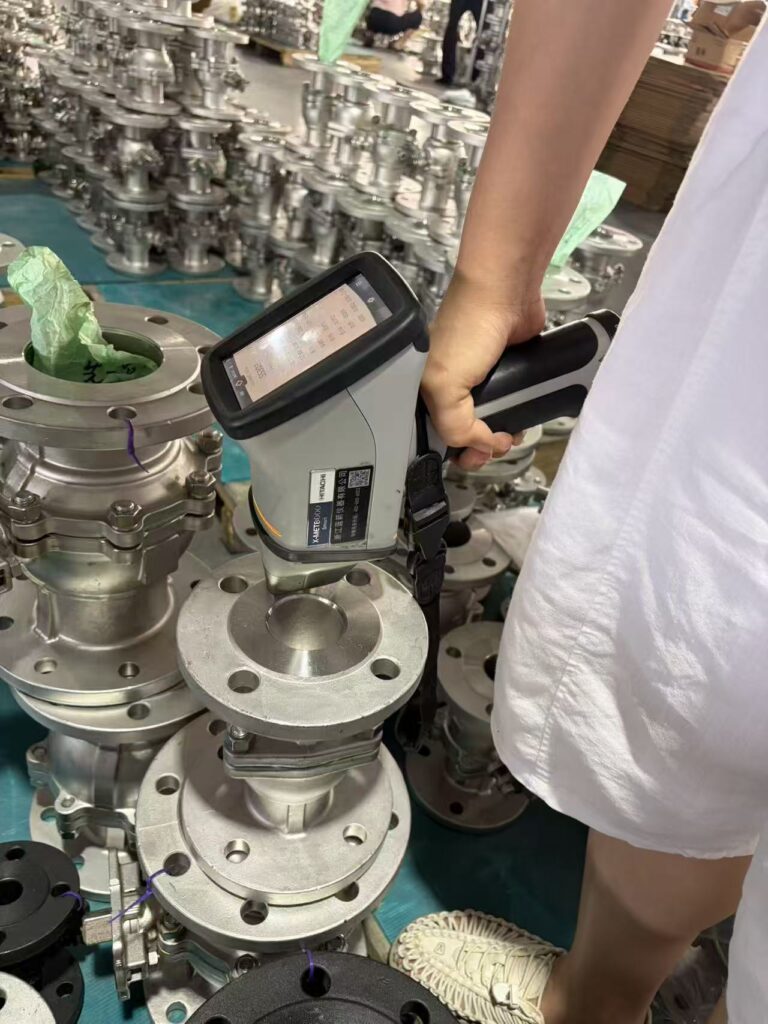 MATERIAL CHECK · SPECTROMETER
Quality records
Mill Test Certificate (EN 10204 3.1) in Every Shipment
- Heat number of the body casting
- Chemical composition against ASTM limits
- Mechanical properties: tensile, yield, elongation
- Shell and seat test pressure and hold time per JB/T 9092
- Signed and stamped by our QC department
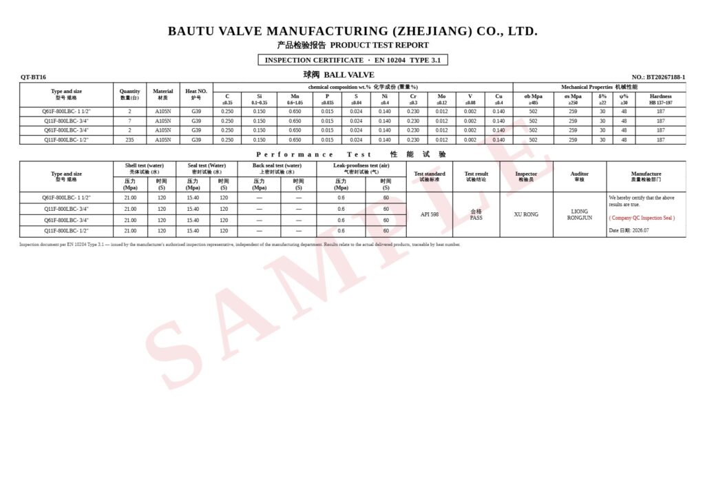 SAMPLE MTC · EN 10204 3.1 · CLICK TO OPEN
We welcome third-party inspection (e.g. SGS or BV), arranged and paid for by the buyer; inspectors get full access to our plant and test bench.
Download Sample MTC (PDF)Made in one plant
From Machining to Crate in Wenzhou
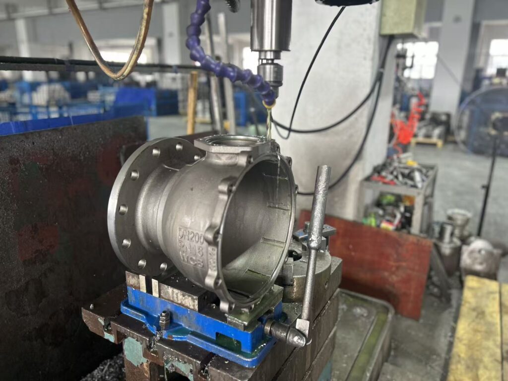 01 MACHINING
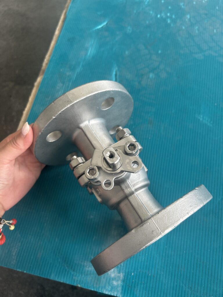
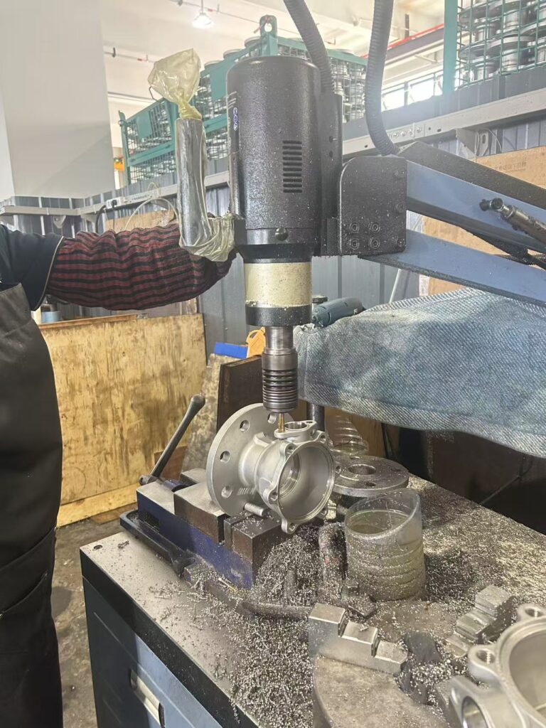 02 DRILLING
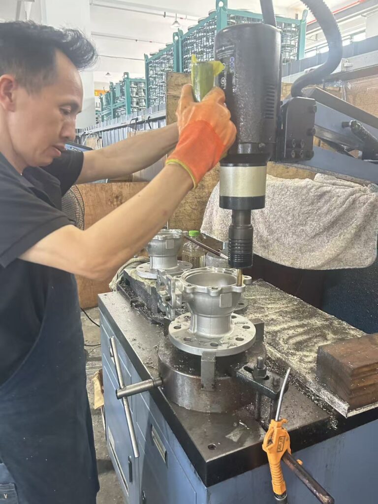 03 ASSEMBLY
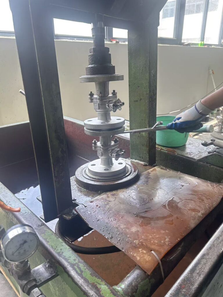 04 PRESSURE TEST
See the valve before you order
Real footage of the valve from our plant. Want to see your own order? Book a live video call and we show your valves on the test bench.
Book a Video Tour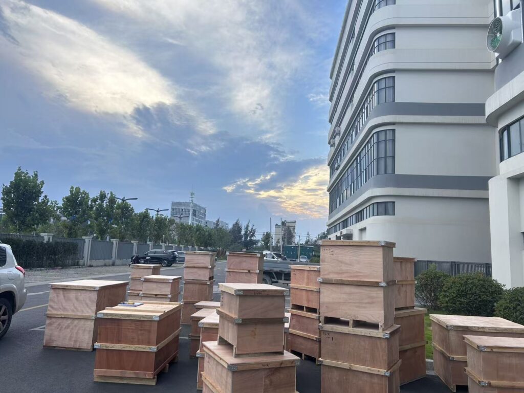 CRATED AT OUR PLANT
Packing & delivery
Packed for Sea Freight
- Flange faces capped to protect the raised face
- Each valve bagged; the order packed in plywood cases
- MTC (EN 10204 3.1) inside every case
- Standard sizes ship in 15–20 days
Related
Related Ball Valves


Need a Quote for This Valve?
Send size, PN, body material and quantity. An engineer replies within 24 hours.